
Many of you have reached out and asked me how do I get internet to my homelab? My setup is a little more complicated than just plugging in an ethernet cable to my existing router. I share my vCenter cluster with my lab and my self-hosted applications. I keep both my lab network and my “production” network separate.
Hi All – Welcome to my channel, I’m Alex Hubbard, I’m a Sr. Sys Admin and Cybersecurity Engineer. I have over 15 years of experience in the IT field. If you’re new to the channel, please subscribe below. If you’ve been here before, welcome back. Be sure to check out my Instagram @ach_sysadmin.
Overview
This overview, assumes that you have some basic knowledge of pFSense, VMware and networking. I want to show you the physical aspect of my lab setup before we jump into VMWare. I won’t get into how I handle my home or “production” network in this video.
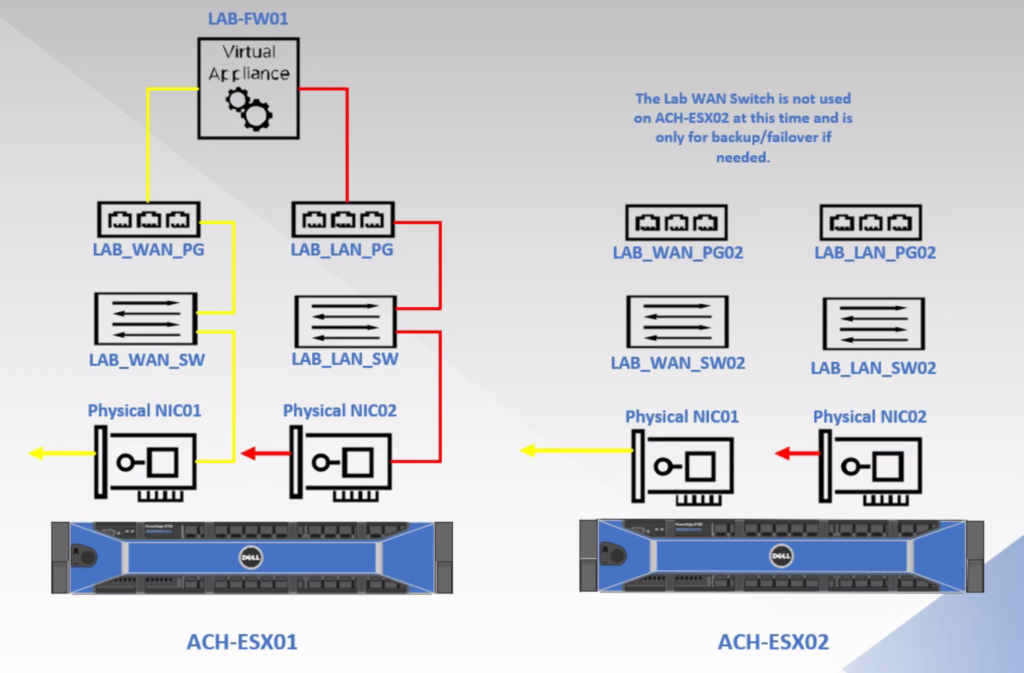
The lab consists of 2 hosts, a Dell R720, which is my ACH-ESX01 host, and a Dell R730 (ACH-ESX02). On the back of an R720 or R730, there are typically 4 NIC cards. Keep in mind, there may be some variations between models. Looking at the system from the back, the NICs are numbered 0-3, left to right. NIC1 on both hosts is my “WAN” connection. NIC2 is my “LAN” connection. This will be important to remember when we jump into VMWare.
I’ve cabled my hosts identically. I’ve also color coded my cabling. Yellow indicates an uplink to a firewall, router or switch. Red indicates LAN or Production.

On my first host, ACH-ESX01, I have a virtual pFSense appliance. This is my lab firewall. We can ignore ACH-ESX02 for the time being as I do not have a virtual firewall on it at this time. So how do we get an internet connection to it?
Physical Network Connections

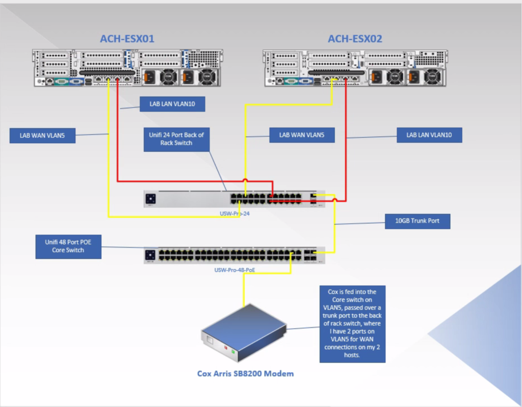
I have two internet connection in my home, but I only feed one of them to my lab. The connection we’ll look at today is my Cox Business connection. I have several static IPs on this account. 1 I use for fail-over for my home, another provides internet to my lab. How do we split that up since the modem only has 1 active LAN port? That’s easy! VLANS!
Ubiquiti Unifi VLAN Setup
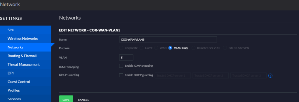
On my Ubiquiti controller, I created a VLAN. I called it COX-WAN-VLAN5 and it’s number is, 5. To do this, make sure you’re in the older/legacy Ubiquiti interface. Navigate to Settings > Networks > Create a New Network > VLAN Only. As a side note, if you’re not in a Unifi environment, you could use an unmanaged switch or create a VLAN on whatever network product you are using to achieve the same result.

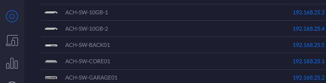
Instead of plugging my Arris SB8200 right into my firewall or UDM-P for my main network, I took the output from the modem, and plugged it into an open port on my Ubiquiti Switch. That port had been assigned to VLAN5. You can assign the port to VLAN5 by going into Devices and finding your switch.

Ubiquiti Unifi Device Configuration – Core Switch
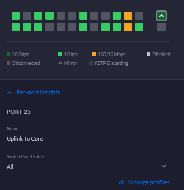
Click on it, and on the right-hand side, you’ll see a menu/window appear. Select the port you connected your modem to. Click it.

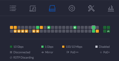
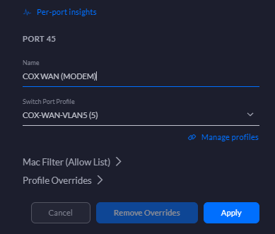
I used Port 45. Select that port, a list of ports will appear. Scroll down and find Port 45 again. Hit the edit button, the little blue pencil.

Give your port a descriptive name so that you know what you’re looking at and don’t have to guess every time. Under Switch Port Profile, find your VLAN5 network. Hit the apply button.

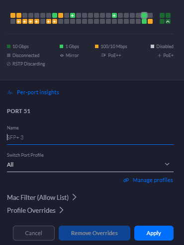
Now we need to send VLAN5 to the back of rack switch, my 24 port Ubiquiti. I have a 10gig trunk port between the two switches.
On my core switch, port 51 is the trunk port. Looking at the switch port profile, you can see it’s set to all.

Ubiquiti Unifi Device Configuration – Back of Rack Switch
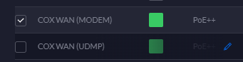
My uplink port on the back of rack switch is also set to the same configuration. We can now access VLAN5 on the back of rack switch.

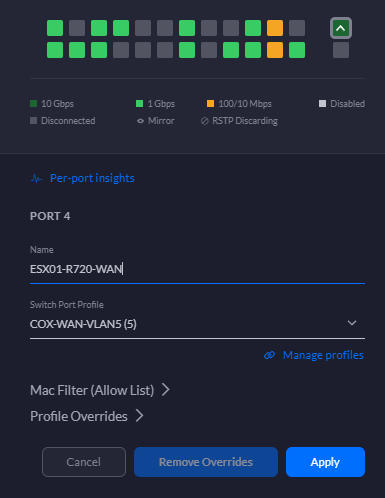
We’re going to take a look at switch port 4 on my back of rack switch, you can see that the Switch Port Profile is set to COX-WAN-VLAN5. This is essentially placing this switch port on VLAN5. This switch port then connects to my host, ACH-ESX01, and presents a WAN connection to the virtual firewall appliance that resides there.

VMware Network Topology
Moving over to our VMWare environment, this is a rough diagram of how things are connected, logically.

VMware Virtual Network Configurations
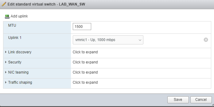
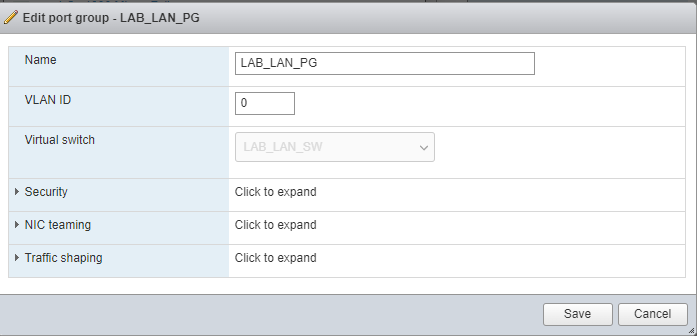
Checking out the Networking section on ESX01, you can see I have LAB_WAN_SW, LAB_LAN_SW and their associated port groups.

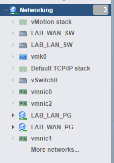
LAB_WAN_SW has an uplink to physical NIC1 (Remember early on I said know the number of the NIC was going to be needed later on?)

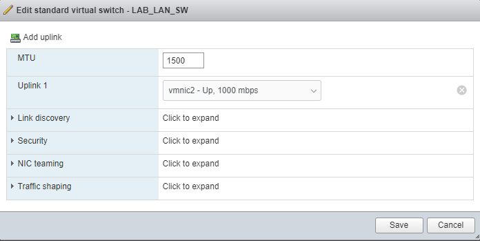
LAB_LAN_SW has an uplink to physical NIC2.

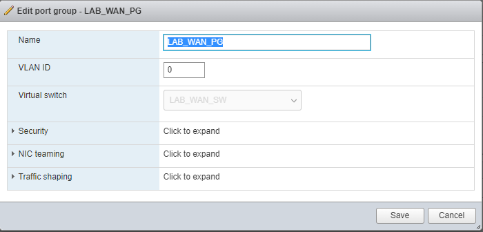
The port group is what is presented to the virtual machine. Think of it as a way to break or divy up your virtual switch.


The LAN side of things is setup identically to the WAN side, with the exception it has a different physical NIC.


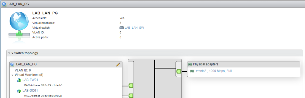
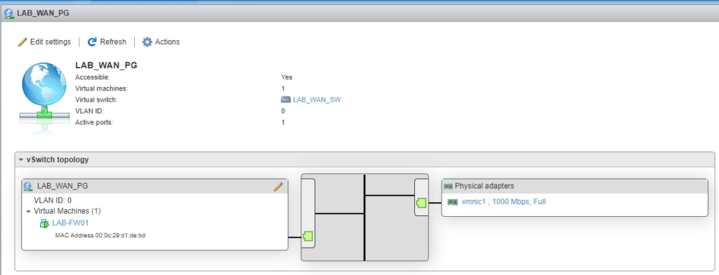
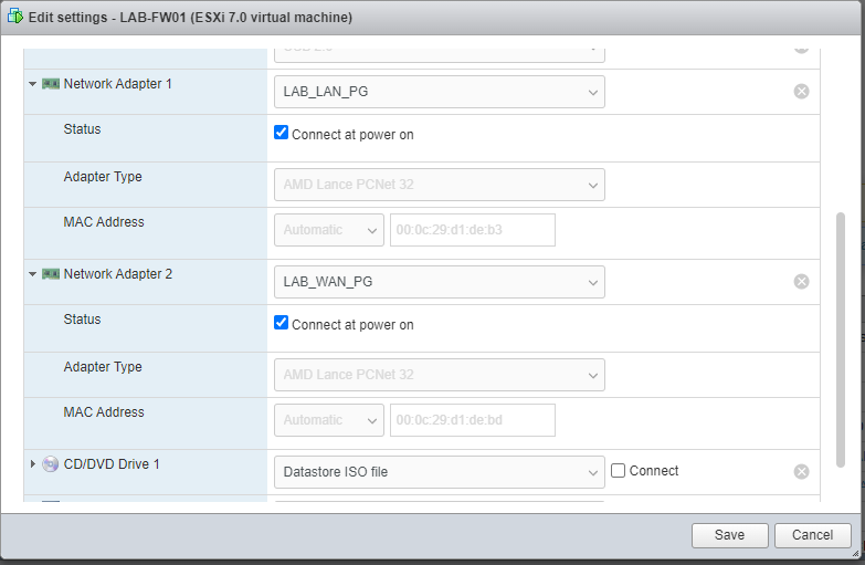
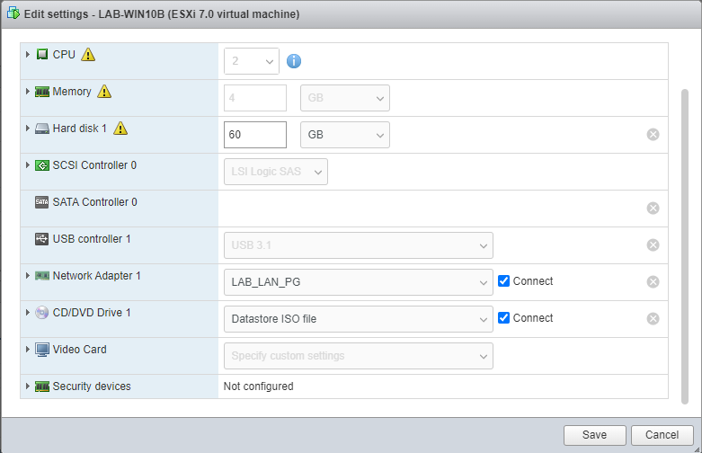
Taking a look at the settings for my virtual firewall, I have 2 network adapters presented to it. 1 on the LAB_LAN_PG and one on the LAB_WAN_PG. You’ll want to note the MAC addresses presented below each NIC

pFSense
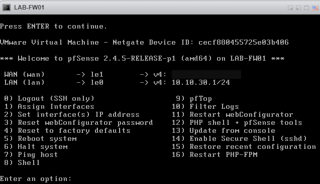
In the pFSense console, you can see we have a WAN and a LAN connection. I’ve already got this setup, but I will show you how you pick your NICs/PGs.

Press 1 to assign interfaces. This is where you’ll need the MAC addresses to distinguish which NIC is which.
00:0c:29:d1:de:b3 is our LAN NIC
00:0c:29:d1:de:bd is our WAN NIC

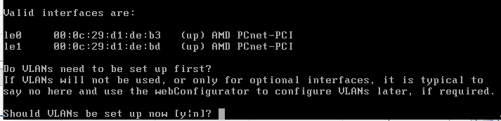
Select No, we are not going to setup VLANs.

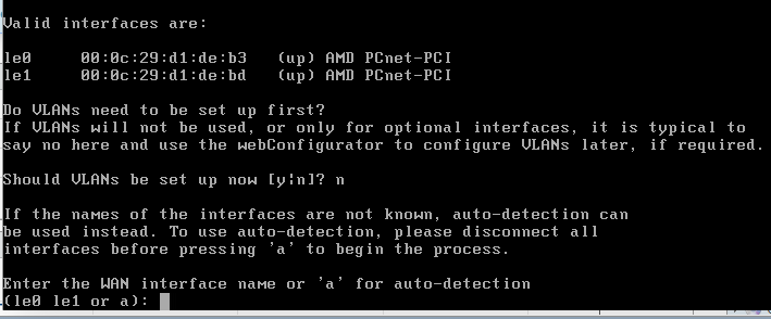
Le1 is going to be our WAN interface. Type le1. I find that auto doesn’t always work.

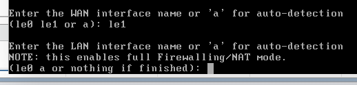
Select le0 for our LAN interface.

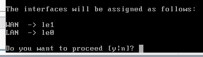
Select Yes.
We will need to set our IP addresses. Select 2 from the main menu.

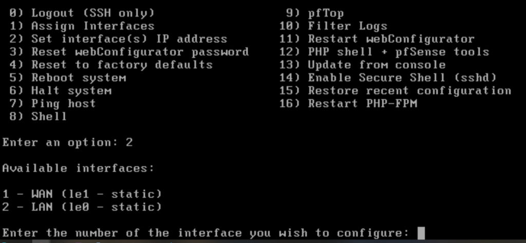
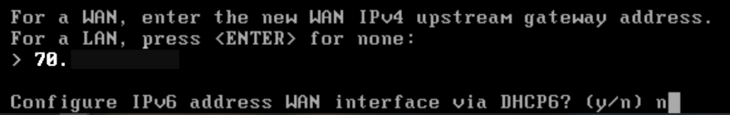
We’ll start with 1, the WAN. Hit 1. Follow the prompts to add your WAN IP, Mask, and Gateway

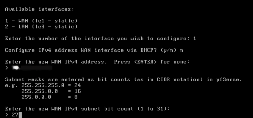
We’re not going to configure it for IPv6, so select no for any questions related to it.


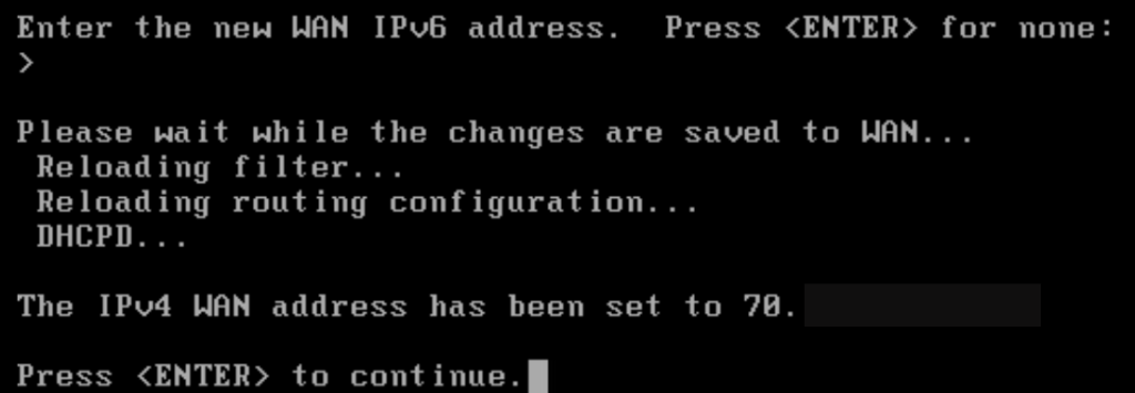
We’ll need to repeat this process for the LAN side of the firewall. Then we can jump into the GUI.
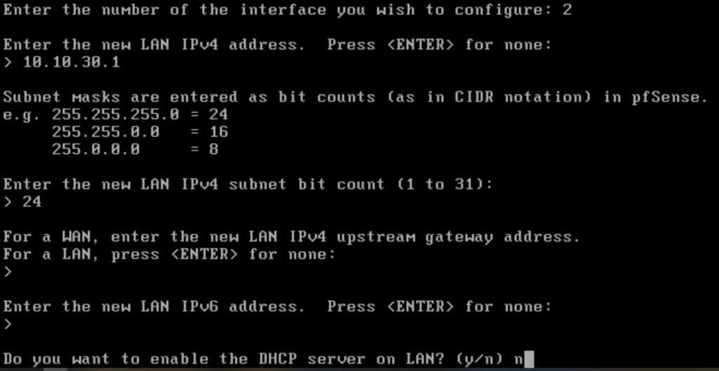
Press 2 again from the main menu.
Select 2 to pick your LAN interface.


Enter the pertinent info for your lab network. I opt not to turn DHCP on as that is handled by my Domain Controller.

Now we’ve got LAN and WAN IPs assigned to our lab firewall. You can hit option 7 and perform a test ping. Let’s ping Google’s public DNS server, 8.8.8.8

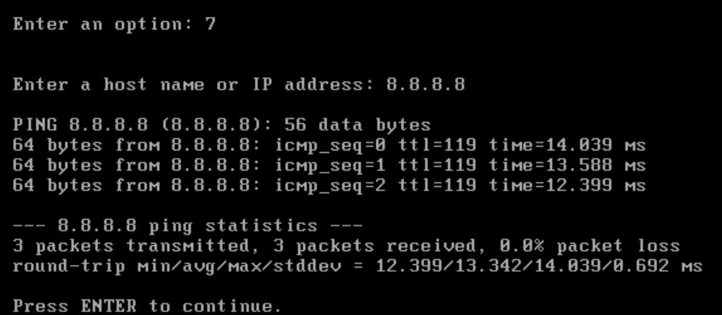
You can see 3 responses, indicating the system can get out to the web.
VMware Virtual Test PC Network Settings
On one of your lab VMs, make sure the network adapter is set to LAB_LAN_PG.

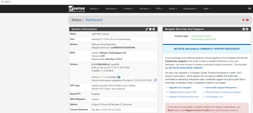
If you opted to enable DHCP on your firewall, you should get an IP address on your lab workstation/VM. I have my LAB-DC01 providing DHCP. Additionally, you could give your system a static IP. Open up a web browser and navigate to the LAN IP of the pFSense firewall and login. You can now administer your firewall from here. You SHOULD be able to open up another browser and hit a webpage.
Also, I use my Domain Controllers for DNS. I do not use pFSense for this.

I hope this overview helped you understand how you can get internet to your lab environment. This is the way that I accomplish it, there are likely other or better ways to accomplish this. If you enjoyed this video, please subscribe and hit that like button below. Give my new Instagram page a follow as well @ach_sysadmin.