
Unifi and NanoStation VLAN Configuration
Background
This is a tutorial on how to configure a VLAN on a Ubiquiti Unifi Controller and switch. We will also go over how to use the second ethernet port on a Ubiquti NanoStation on a different VLAN for use with a Ubiquiti Security Camera.
I have a rather long driveway, our upper half of the driveway is where my office and house are located. The lower half houses an area for our growing animal population and parking. I have multiple VLANs, 1 of which is for my security cameras. I wanted the 2nd port on the Ubiquiti NanoStation placed on the lower portion of the driveway to be able to utilize my camera VLAN.
This tutorial will assume that all of the hardware is in place and you are ready to make the secondary ethernet port on the NanoStation work on another VLAN.
In my case, I have a Unifi Controller that will need to be configured with my security VLAN, VLAN35, prior to configuring my NanoStations.
Unfi Configuration
Enter the Unifi controller and navigate to Settings >Networks. 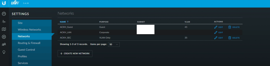
Click on the “Create New Network” button. Select “VLAN Only” from the “Purpose” section. Give your VLAN a name and a number. I chose 35.
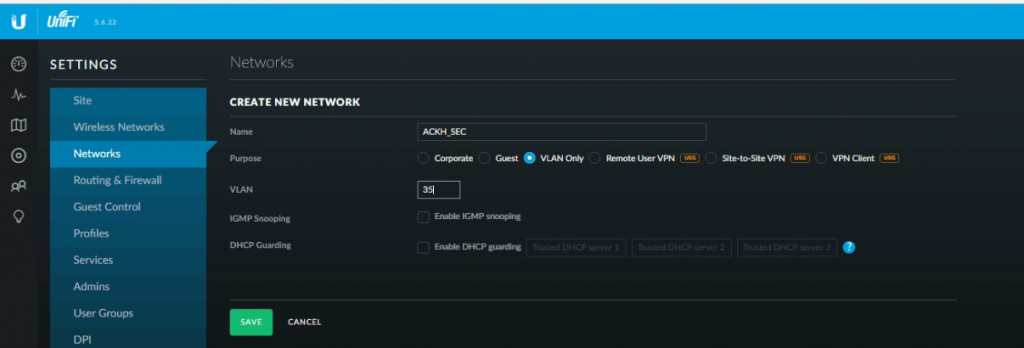
You can then configure any other settings for your new VLAN that you may need. In my case, I only needed the basics. No DHCP on my security VLAN. You can then click on the “Save” button.
Once saved, in the Unifi controller, navigate to “Devices”
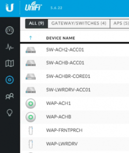
Select your switch and it will open the device’s configurations on the right hand side of the page. Select your port from the list and click “Edit”
On my “Core” (I use quotations because it is not really a core switch, but it is my main switch) I picked port 2 to use for my NanoStation uplink.
You want to make sure the “Switch Port Profile” is set to “All” – The reason is that this port is going to act as a trunk port and provide all of the VLANs to your first NanoStation. You want this if you wish to pass all of your VLANs over the bridge. Click “Apply”

NanoStation Station 1 Configuration
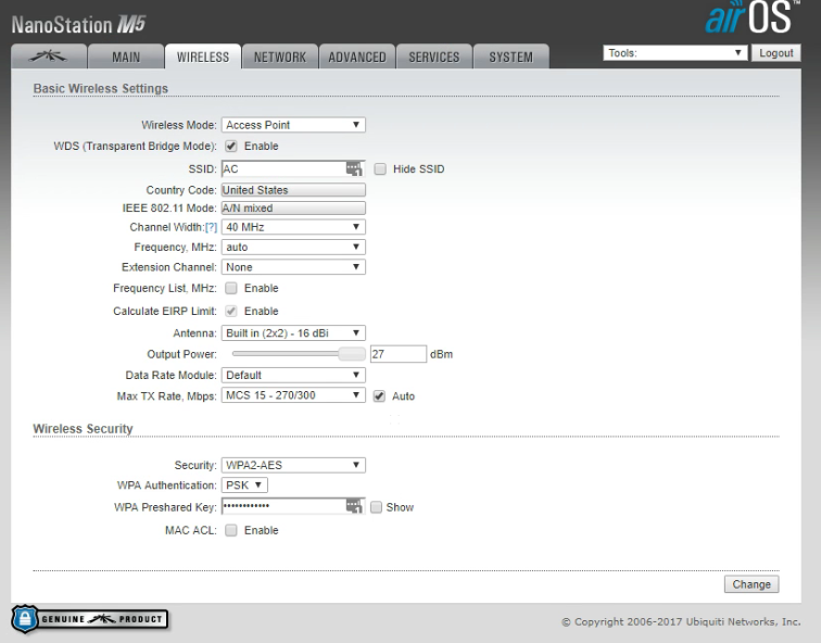
Next, login to the web interface of your NanoStation that will be acting as the “Station” – Navigate to the “Wireless” tab. Here you want to configure your wireless bridge settings (IE: your SSID, WPA2 Key, Channel Width etc) – I will leave that up to you to determine what works for your application. Since this NanoStation is acting as the “Station” you want to make sure the “Wireless Mode” is set to “Station”
Below is what I chose for my settings:
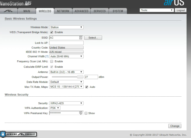
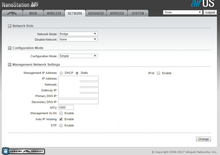
Once the wireless portion of your first station is configured, go to the “Network” tab. Here you can configure your station with a static IP etc. For the purposes of this tutorial, we will assume you have already given your station a static IP address, gateway, mask, DNS and so forth. You will want to make sure that the “Network Mode” is set to “Bridge” and that the “Configuration Mode” is set to “Simple”
NanoStation Station 2 Configuration
After completing the setup of your first NanoStation, login to the web interface of the second NanoStation. First go to the “Wireless” tab on your second NanoStation. This time you will want “Wireless Mode” to be set as “Access Point” – You will then match the rest of the settings to the settings you configured on the “Wireless” tab on your first NanoStation.
Once you have selected your settings, navigate to the “Network” tab on your second NanoStation. This is where things get to be a little be more complex. Since the wireless bridge itself is passing all of the VLANs across it, we need to tell the NanoStation what VLAN to use for the 2nd onboard ethernet port. This is the port we will be daisy chaining our camera off of.
VLAN and Bridge Configuration
On station number 2, your “Network Mode” will also be set to “Bridge”, you will have the option to set a static IP, mask, gateway and so forth. The real difference here is that the “Configuration Mode” MUST be set to “Advanced” this will open up a slew of different options for you.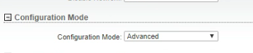
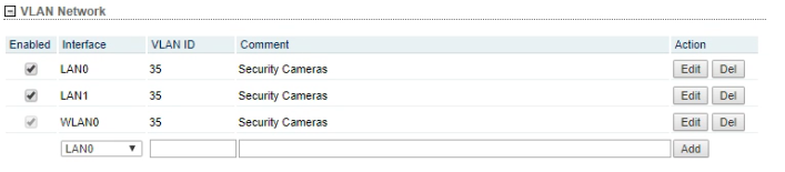
When “Advanced” is selected, you will now see a bunch of options at the bottom of the page. For this example, the LAN0 port is feeding a switch, the LAN1 port is what the camera will be daisy chained off of and WLAN0 is the wireless bridge between the two NanoStations.
Under the VLAN Network section, we first must add VLAN35 to each interface. This will allow the NanoStation to pass VLAN 35 over the wireless bridge and the 2 ethernet ports.
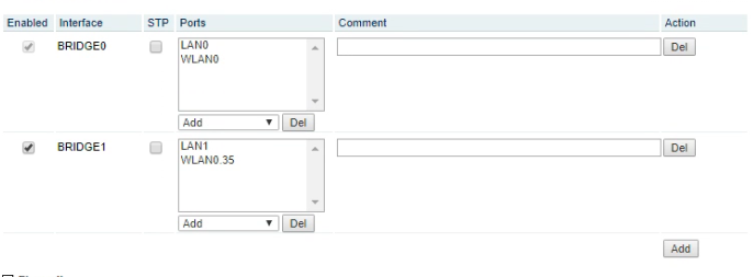
After adding the VLAN to the interfaces, come on down to the “Bridge Network” section. If memory serves me correctly, you must break the existing bridge to configure a new bridge.
BRIDGE0 is allowing LAN0 and WLAN0 to communicate thus passing management traffic to the switch connected to that ethernet port.
BRIDGE1 is allowing LAN1 and WLAN0.35 to communicate thus allowing camera traffic to pass from LAN1 to the wireless bridge, and back to the NVR.
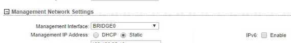
After configuring the bridges, you must go up to the “Management Network Settings” section. Select “Management Interface”, in my case, it is “BRIDGE0” or my “management” VLAN.
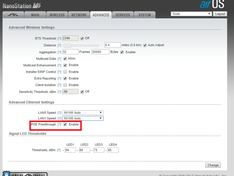
The final step before you can plug the camera in, is to enable POE Passthrough. This allows the NanoStation to power the camera via POE on the secondary LAN port. On your second NanoStation, navigate to the “Advanced” tab. Scroll down until you find “Advanced Ethernet Settings”. Check the checkbox labeled “POE Passthrough enabled”. Click the change button and you should now be able to power up your camera on a separate VLAN.
Hope this helps someone, I spent a lot of time trying to get this to work on my property.